Here is a very brief description for safety instrumented systems to get you started into functional safety.
The IEC defines a Safety Instrumented System (SIS) as “an instrumented system used to implement one or more safety instrumented functions (SIF). A SIS is composed of any combination of sensor(s), logic solver(s), and final element(s)” (IEC 61511 / ISA SP 84.01)
The amount of sensing element(s), logic solver(s), and final element(s) is determined by the required Safety Integrity Level (SIL) that has been defined for a SIF.
There are many different terms for a SIS PLCs, that being one of them. Some other terms that you may come across are; Programmable Electronic System (PES), Logic Solver, Safety PLC, ect…. All of these terms are interchangeable and can refer to the same piece of equipment.
Safety Integrity Level (SIL)
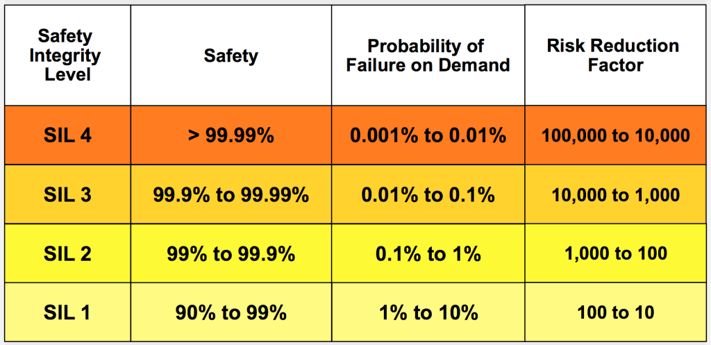
Definition – The Safety Integrity Level of a specific Safety Instrumented Function (SIF) which is being implemented by a Safety Instrumented System (SIS).
To really understand a SIL rating you need to know what the Probability of Failure on Demand (PFD) is. The PFD is a likelihood that a loop will fail when a demand is placed on it. The PFD of a SIF is calculated using the number of potential dangerous undetected failures and the test interval of the loop.
Safety instrumented systems are used to implement SIFs as layers of protection to reduce process hazards. Its an automated way to take an action against a potentially unsafe condition and return a process to a safe or stable state.
Some major differences between a SIS PLC and BPCS hardware are;
- a Standard BPCS has unknown failure modes
- a SIS PLC will fail safely within a specified probability (SIL)
- a SIS PLC is certified to standards like IEC61508 for use in a safety application
- Safety PLC must be configured by person with appropriate competency in both safety and the development platform.
A single SIS PLC can have any number of safety instrumented functions being controlled within it depending on how many unsafe conditions can exist in a facility, or area of a facility. Most safety loops are designed to be configured as a de-energize to trip system, where the SIS PLC must remove power to trip the loop.
Sensing elements that are typically connected to a SIS are Pressure Transmitters, Level Transmitters, Temperature Transmitters, Flame Detectors, Smoke Detectors, Toxic Gas Detectors, Emergency Shut Down (ESD) switches, and any number of input devices.
Final elements are typically Solenoid Operated Valves (SOV), Beacons, Horns, Exhaust Fans, and Doors to name a few.
One thing to always keep in mind is that a SIS is not just a controller for a system. A SIS includes all transmitters and final elements, as well as associated solenoids, exhaust valves, and loop splitters. Any component where its failure could cause a potential failure on the loop is a component that is included in the SIS.

Some processes where you will typically see a SIS will be burner management systems (BMS), High Integrity Pressure Protection Systems (HIPPS), Emergency Shutdown Systems (ESD), and Fire and Gas Detection Systems. These systems are all in control of very dangerous processes where a large amount of risk exists.
In Summary
A SIS includes field sensing devices, controllers, and final elements. All of these components must be certified for use in the respective application with a respective SIL rating. A SIS is installed in order to mitigate risk and return processes to a safe state automatically upon a demand.
There are a tonne of acronyms involved in functional safety and i’ve tried to define all of the ones I use within this post. If i’ve forgotten one or if you have any questions while reading this post a comment below and I will answer.

